Transverter Interfacing
by N2CEI
You have purchased a brand new high performance HF transceiver
and are more than pleased with it when you decide that you would
like to interface your 2 meter transverter to it. Why not it
worked great with the old rig, it should work even better with
the new one! ------------Well, ---------You start to hook it up
and soon realize that its not quite as simple as the last setup
you had. This paper will discuss many different methods of interfacing
transverters that solely depend on the type of transceiver being
used. The transceiver types will be put into categories but
commercial names and model numbers will only be used if the transceiver
is unique.
Some of the first transverters that early experimenters designed,
and some manufactures provided, required high TX drive levels
compared to today's standards. This generation of transverters
used Vacuum tubes for both transmit and receive and were very
forgiving about exact transmit drive levels. You would tune and
adjust them just as if they were a power amplifier. Most of the
time you would be using a separate transmitter and receiver so
interfacing was considered fairly simple to the ham of that era. Drive levels were set by indications of plate current in the
transmit converter or presetting the drive level of your transmitter
for a dim glow in a No. 47 pilot lamp! It was a bit of a guess
but out of this new wave of VHF operation came the circuit in
Figure 1.
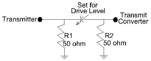
Figure 1.
The conceptof Figure 1. is now the basis for
any solid state transverter that will tolerate more than 200 mW
of drive. This circuit may be used with transmitters and transceivers
that have high output power levels by increasing the wattage rating
of R1 or using a large dummy load as in fig 2. If you set the
adjustable attenuator (the variable capacitor) to the maximum
level required by the transverter, then the transverters power
output can be decreased by decreasing the transmit power of
the transmitter. Then be sure to use a non radiating load or
you will also be working the 10 meter band when 6 meters is open!
Also use good quality coax and place the adjustable capacitor
and loads in a RF tight enclosure.
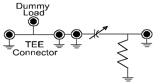
Figure 2
To use Figure 2. with a transceiver, simply add a transfer relay
on your transceiver before the dummy load circuit. Then use the
keying circuit (that would be used to key an external amplifier)
to toggle the transfer relay form the receive to transmit position.
A RF sensed circuit is not recommended for full break in or SSB
operation unless a large amount of "Hang Time" is designed
into the circuit to prevent relay chatter (but then full break
in would not work anyway!). In figure 3, the receive side of the
relay would go directly to the transverters receive output port.
If you are using a transverter that has both receive and transmit
IF ports combined, add a transfer relay to the transverter side
of the circuit, and switch both of them together. This can be
a low power relay in most cases, but keep it coaxial if it is
external to the transverter

Figure 3
To consolidate space , the mechanical relays in figure 3 can
be replaced with a solid state switching circuit. (PIN diodes)
With the use of a low power 50 ohm load or a network of resistors
you will have the standard switching circuit used in microwave
transverters that use low power portable 2 meter transceivers
as IFs . Figure 4. Is an example of this circuit and can be interfaced
directly to the transverter or put into a separate enclosure if
the radiated RF from the load resistor is a problem.
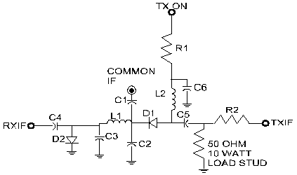
Figure 4.
Further enhancements to figure 4. may be added to provide DC switching
for the RX and TX sections of a transverter and a extra RX gain
stage if needed. Figure 5. Shows a circuit that can also provide
external DC for other gain stages such as Preamplifiers and TR
switches. Adjustable attenuators for trimming the required amounts
of gain on both TX and RX may also be added. This is standard
on most microwave transverter kits today. It is found built in
to transverter PC boards and as separate add on circuits.
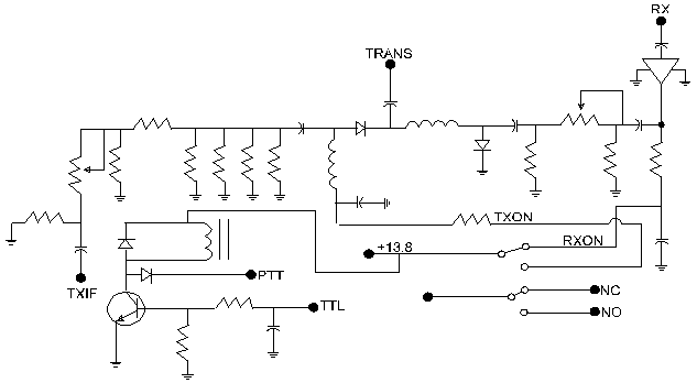
Figure 5.
Adding keying line circuits are simple and a effective way to
make a easy to use portable station. RF senescing should be avoided
to eliminate relay chatter, and a positive keying circuit should
be used. The TXON point of fig. 4 or the TTL of Figure 5. requires
a positive voltage that can be found in most 2 meter transceivers.
Some are external and others are found on the coax line during
transmit. To use this positive keying voltage, a RF choke is connected
between the common IF connector (from the transceiver) and the
TXON (or TTL) point on the schematic. Be sure to use a bypass
capacitor to de-couple the RF from the switching circuit.
L1 ,C2 and C3 in figure 4. are frequency sensitive and can be
selected for any frequency IF. This circuit has been use with
903 and 1296 MHz. IFs but will have considerable loss and low
isolation if leaded components are used. Surface mount diodes,
capacitors and small, tightly wound inductors should be carefully
laid out on a circuit board for best results.
If it is absolutely necessary to use RF sensing, adding
a circuit with some hysteresis and delay to Figure 4. by using
an op-amp and some high value capacitors for "Hang Time"
will make a switching circuit that will enable any transceiver
to be interfaced with any transverter. Just be careful of the
power dissipation of the 50 ohm load.( See Figure 6.) This circuit
will still fit into a small enclosure with a heatsink attached
or could be mounted inside a transverter if the RF power levels
are low enough to prevent radiation into the mixer circuits. Dissipation
of 100 watts might be a little difficult inside of a transverters
enclosure but it could be done with a large enough heatsink.
C12, C13, and L2 are the frequency selective components.
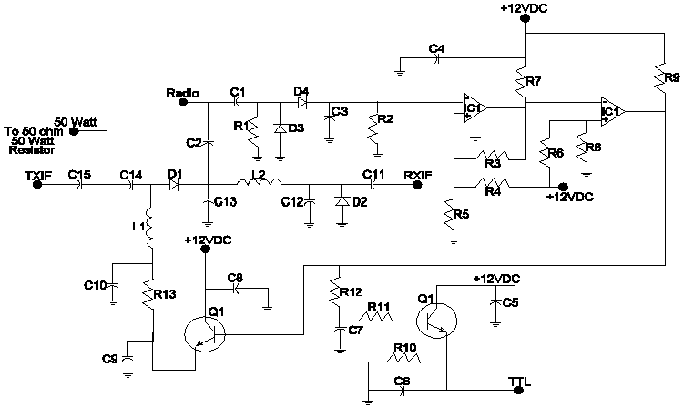
Figure 6.
A further consideration would be to add a sequenced circuit such
as in N1BWT's "Fool Resistant Switch" (Fig. 7.) This
circuit is a sequencer coupled with the basic circuit found in
Fig. 4 . It provides separate sequenced output voltages to all
gain stages and preamplifiers. It has RF sensing built in but
has options to enable or disable it. It also has just about
any feed back and switching circuit required to set up a high
performance microwave transverter system with mast mounted LNAs
and TWTs
Transverter Interface
Box (TIB)
With most of the newer transceivers having the best receivers
amateur radio operators ever had available to them , makes it
a natural to want to connect a transverter to it. Finding out
it doesn't have a transverter port is sometimes a let down. So
far the discussion has been how to interface transceivers to
transverters that are basically less than 25 watts of power. The
higher power examples work, but having a 100 watt dummy load connected
to your transverter system not only wastes energy and produces
heat, it is a bit cumbersome if you plan to operate portable. There should be a better way and there is. The use of the "ALC"
circuit that is built in to most HF transceivers is one way to
save a lot of energy and hardware .
The ALC circuit found in most HF transceivers has a external connection
that is intended to be connected to a linear amplifier. The
theory is that when the amplifier becomes overdriven, it will
produce a negative voltage that is feed back into the transceiver's
ALC circuitry. This voltage acts as a gain control in the transmit
stages of the transceiver. This in turn, lowers the drive power
automatically (the transceivers output power) and limits distortion
from a overdriven amplifier. What a great idea! So, why not use
it in a transverter system. Not as a feed back system to limit
distortion, (that is done by a proper drive level setting of the
transverter) but as a power limiting circuit in your transceiver.
There isn't a transceiver with a ALC circuit that can't be totally
disabled with a negative voltage input! That's right! Negative
voltage input. This can be tested on any transceiver with a variable
supply(isolate the ground!) or use a 9 Volt battery and a multi-turn
pot. After connecting your transceiver to a power meter, slowly
increase the amount of negative voltage on the ALC input and watch
the power output drop! You now have control of the power output
of your transceiver. Connect a transfer relay system between your
transceiver and transverter to handle the Transmit and receive
functions and go get 'em!
Well, almost! There are a few things you need to be aware of when
using a circuit like this. Don't use a 9 volt battery in a permanent
set-up. When the battery goes dead, so does you transverter! Use
a Negative voltage generator such as a ICL 7660 circuit similar
to a LNA GaAs-FET power supply. ALC circuits require only a few
milliamps of current It should be interfaced so that when the
transverter is in line, the negative voltage is on! Also set
it up so the default position of your system is your transceiver
connected to a load other than your transverter!! (That would
work that VSWR protection circuit!)
Still after you set that up, there are a few other items to be
aware of. Some ALC circuits behave differently in different modes
of operation. Switching from SSB to FM could be a nightmare! Check
the output power in both modes. Some other transceivers sometimes
generate a spike on initial transmit. This could cause damage
to your TX mixer so check it out. This spike could be caused from
not enough negative voltage. Also be sure the negative voltage
is on the ALC input 100% of the time. Don't just switch it in
on transmit!
When adjusting the voltage level on your ALC circuit, try to
totally disable the transmitters power output. It will bottom
out at a very low level output. Some around 1-2 milliwatts. Then
give it a little more negative voltage if possible. Even if your
transceiver says 0 to -4VDC, minus 9 VDC will work just fine
on all ALC circuits. If you try to adjust the power output of
your transceiver with the negative voltage, you will find a point
in the curve that a small change in negative voltage will produce
a large change in output power. Stay away from that point. It
is too unstable! Set you transverter system up with the minimum
amount of drive possible. It just make levels more manageable
Figure 8. shows a fool proof circuit.
The rest of the Story!
There are still a few transceivers on the market that had to be
different. For one reason or another, after establishing a precedent,
somebody decides to change the method. Going from a simple Din
plug connection of the past to needing to build a "Bias Tee"
in the future doesn't sound like progress! You guessed it! The
TS-850! It's is a less than desirable setup because if you lose
the voltage on the assembled "Bias Tee" you will transmit
into the RXIF of your transverter. The other draw back is that
when you want to use the rig on the Low bands, you need to dis-connect
everything!
So a interface is required. See Figure 9. When the circuit is shut off, the standard RF path is routed through the relays. (transmit and receive) When the circuit is power up, a regulated voltage
is sent to the transverter connection on the TS-850. This voltage
disables the transmitter in the TS-850. This in turn ensures
that the 850 will not transmit in to the RXIF port of the transverter
which is now connected by the internal RF relay in the circuit.(Yes!
The only RX IN is the main antenna connector!) The best feature
of this circuit is that the default is when the circuit does not
have DC voltage applied.
Figure 10. shows a circuit used with a FT-757GX . It has the
same draw back as the TS-850. The RXIF port from a transverter
is connected to the main antenna connection. Ouch!------------
A good point is that it has a connection that can be interfaced
to a transverter system with a simple switch. A jumper in the
main power connector is replaced with a switch and that will put
the transceiver in transverter mode or not. This switch should
also be connected to the RF relay the will either connect a HF
antenna or the transverter's RXIF line to the main antenna connection.
Again, the default is normal HF operation with the DC power
off! Only other hitch in the FT-757GX is that it has a low level
drive signal for a transverter,(-6dBm or less) and the push
to talk to ground key line will only sink up to 2 ma. You should
use this signal to activate a relay to key all other accessories.
This is an important note. Most of the newer transceivers on the
market today do not have mechanical relays as auxiliary connections
for activating amplifier or transverter circuits. High current
open collector circuits don't exist either. Most key circuits
will only sink or source a few milliamps. Read the manual and
if you get can't find the answer, call some one! Don't just try
it unless you are ready to replace a SMD transistor if you can
find the blown transistor!
A common set up for most Icom transceivers with transverter
ports, would be to connect the transverter port of the transceiver
to the TXIF of the transverter. Then connect the RXIF to one of
the auxiliary antenna connectors. Well this has changed with
the newer Icoms. The transverter port is used for both transmit
and receive. The circuit in Figure 11. can be installed into
the transverter so it becomes a simple setup. But the new trick
in the IC 765 and 775 is to toggle the voltage on pin 6 of the
accessory jack on and off when changing from transmit to receive.
This should be done with an external set of relay contacts in
the transverter . Use the "Send" line in the transceiver
to key the transverter.
Some other general notes are to watch out for rigs that say they
are transverter ready. A few on the market today do little more
than change the frequency readout on the digital display!! Watch
it! If you are in the market for a new rig and think you may
want to use it with a transverter system, ask all of the questions!
Sometimes a letter designator such as "D" or "MP"
will make the difference between a simply or a complex interconnection.
They all can be interfaced but why not catch a break every now
and then.
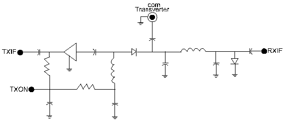
Figure 11.
Conclusion
This paper has not covered everything there is to know about transverter
interfacing. I am sure some one could pull out a new or a old
rig that just "hasn't been done before". I am sure the
major manufactures will not disappoint us in their cleverness
to save a few pennies buy using a new connector or method of providing
what they think a transverter should need. The days when external
ports on plug-in computer boards to interface our transverters
are not far away. It is a fact that major manufactures are trying
to replace the need for most transverters with their newest offerings.
A rig that will operate from 160M through 23 cm is also not very
far away! But, the newest Satellite rigs have internal connections
that are waiting for the launch of Phase IIID. If the major manufactures
will provide the interfacing or converters for these transceivers
remains to be seen
Being the Hams we are, we will always have a need to experiment
or find our selves just not satisfied with the standard transceivers
performance. With QSO's being conducted in the microwave regions
becoming commonplace and future microwave satellites ready to
be launched, there will always be a need to interface some sort
of converter to a transceiver. We will see.
Have fun and catch you on the bands!


