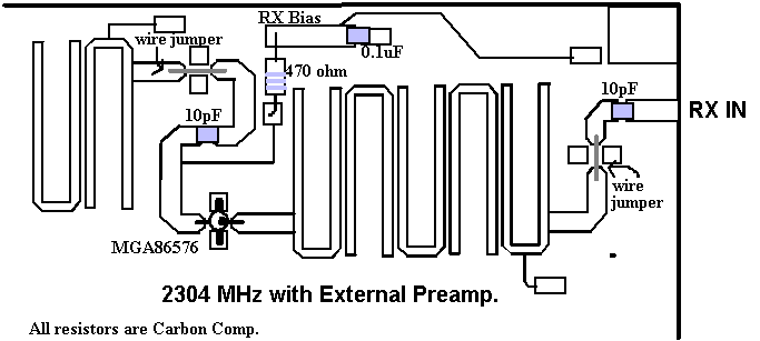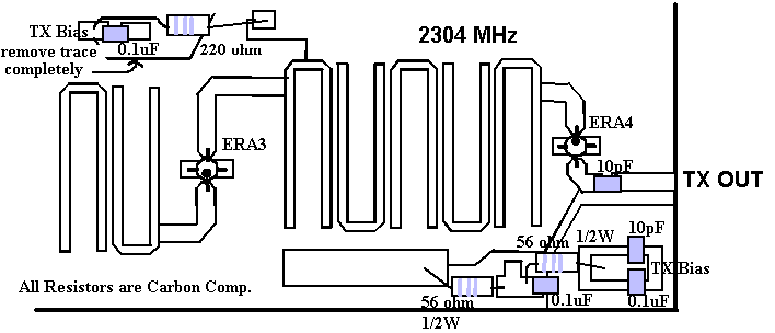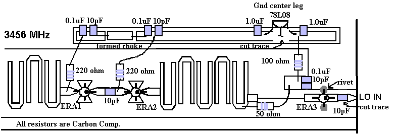
Since the introduction of the "NO-TUNE" transverters in the late 1980's Monolithic Microwave Integrated Circuits, MMIC's , have greatly improved in performance and yet remained economical enough for amateur use. This article will discuss various options and some results in improving the performance of the two transverters originally designed by Jim Davey, WA8LNC. The 3 basic issues that will be covered will be Receiver Performance and Options, Transmit Power and Purity, and Local Oscillator Multiplication. Both transverters will be discussed simultaneously allowing comparisons to be made in construction and end results with some words on construction technique. Since detailed drawings of component placement are included, it was not found necessary to include schematics.
When the receiver sections of the 2 transverters were originally designed, MMIC's with noise figures of less than 4 dB were not economically available to most amateurs. Although low noise GaAs-FET preamplifiers designs that were being used by hams were considered, they required special bias supplies and a large amount of circuit board space. With the scope of the project being simplicity and repeatability, and driven by economics, GaAs-FET's were deemed not practical to implement into a simple transverter design. Today, with the advent of affordable GaAs-FET MMIC's, we now have stable drop-in, or with a little circuit modification, designs that will have less than a 2 dB NF and over 20 dB gain. The HP/Avantek MGA86576 became the MMIC of choice for both units (fig. 1. & 2.). It replaces the first MAR 6 MMIC, in both transverters and will produce a 2-3 dB NF improvement. (see table 1 for approximate specifications of the MGA86576) The transverter's noise figure could be optimized for >2dB by performing the input circuit modification shown. With the increased gain that the MGA86576 offers, the proceeding MMIC's should be completely removed on the 3456 transverter. On the 2304 unit, remove the second gain stage (between the filters) and replace the third stage with a MAR 2. If you plan to use an external GaAs-FET LNA with the 2304 transverter, (fig. 3) remove all three gain stages and install the MGA86576 MMIC in the 2nd stage position, between the two band pass filters, to ensure that the out of band products amplified by the pre-amp are filtered out. If an external LNA is to be used with the 3456 transverter, (fig. 4) a filter should be installed (pipe cap) ahead of the transverter. It will not be necessary to perform the low noise figure modification on the MGA86576 if it is used as a second stage.
When implementing these changes, check all ground wraps and/or
ground rivets. Be sure they are as flat as possible and are clean
connections. The MGA86576 will oscillate if there is and excessive
amount of inductance on it's ground leads. Also verify that there
is a good ground connection at every by-pass capacitor! If you
are modifying an old board, oxidized, missing, or broken ground
connections could have been the original problem keeping the transverter
from working in the first place. Take you time in checking them
out this time (Its a thought!).


With the introduction of Mini Circuit Laboratory's ERA series of MMIC's ( table 2 ), it is now possible to have as much as 100 mW of output power on both bands. Both transverters used a MAR-8 as a final power amplifier that at times because of it's low frequency gain, became very unstable. If you managed to tame it down, 5 to 10 mW output was a realistic. There were a few mods that incorporated a single gate GaAs-FET as a replacement, but they were not a drop-in solution. The other problem with the TX circuit was that the radiated LO signals, fundamental and multiplied , would conduct into the final gain stage and became amplified to levels as much as -10dBc. The radiated LO is a separate problem and will be addressed later in this article, but with the new MMIC's and a brief explanation, both problems will be improved on.
The 2304 transverter uses 2 gain stages on the TX side, a MAR 3 and a MAR 8. Remove both of them. The 2304 PCB design (REV. D) only cycles the bias on the output MMIC. This needs to be changed so the TX bias is only on during TX for both stages. Perform the suggested modification to the circuit board in fig.5.(Cut and remove the trace!) For a cleaner than original signal, install a ERA-3 in the position between the 2 filters . This is all that is needed for 10 to 15 mW of output. If higher output is desired, a ERA-4 could be installed in the final output position. (fig. 6) If the LO is not modified, expect to see close to 100 mW output at 2304 and as much as 10 mW of output at 2160. This might be OK if you plan to use a extra band pass filter on the output before amplifying it by any other gain stages. If other output levels are required, select any other MMIC that meets your specification.
The 3456 transverter is very similar to the 2304 unit but it used 3 gain stages in the TX chain. Remove all of them. In this design, you have a little more flexibility. If you figure a clean -15dBm out of the mixer/filter combination, decide what you would want for an output , refer to table 2 and do the math. Only recommendations are not to cascade any other MMIC with an ERA-3 between the 2 band pass filters. A good combination (fig 7.) would be to use a ERA-2 driving a ERA-1 between the filters. This alone will produce 10 -15 mW of output. If higher power is desired, an ERA-3 between the two filters driving a ERA-4 final (fig. 8 ) will deliver up to 100 mW output but will require a external band pass filter if additional gain stages are to be used . Again it is recommended that the LO chain be modified to improve the spectral purity.
Like in the receive section, care must be taken in the assembly
and to be sure about the grounding. If there are any doubts, fix
it. Also if using the ERA-4's or 5's, care must be taken because
they will dissipate allot more power than the older MMIC's. 1/2
w resistors get real warm! If you make a resistor change, do the
math!


The most difficulty encountered in using both transverters has always been caused by the 4X and 6X multiplier circuits. There have been many fixes and cures published and talked about, but the problems still remained. The major problem being the high level of 540 & 552 MHz. energy injected into the harmonic generator circuit would be reflected back or radiated resulting in a starved amplifier chain which would allow it to oscillate at its own desired frequency. With 2 fundamental oscillators now being introduced to the mixers, (the main and the self oscillator ) it is easy to understand why the transverters worked sometimes really well and not so good all of the other times. Receiver noise is a good indication of operation but at what frequency would it be at if the LO chain had it's own frequency being generated? Both transverters have fooled many noise figure meters. If any of the mods are performed on the two transverters, the LO chain modification would put you on the right track in fixing all of the transverter's other problems.
After reading a article published by Jim Dave on Frequency Multipliers and discussing it with him, I found that it was possible to implement this idea into both transverters with little difficulty and produce huge results. Using the ERA-3 as the MMIC multiplier, it was found that a "sweet spot " existed as far as drive level verses operating voltage. A voltage was derived to allow a LO drive of +0dbm with a plus or minus delta of 3db to be used. Remove all of the components and reassemble per fig. 9 & fig. 10 When installing the ERA-3 multiplier, care must be taken in proper placement and grounding. New ground pads need to be formed with rivets. As for the amplifier section, all of the instability of the MAR-8 MMIC's are eliminated along with the radiation effect. The new multiplier chain will deliver 10 mW of LO drive to the power dividers with out even winding a coil and having nothing to tune.
The standard LO designed by Rick Campbell, KK7B will need the
final MMIC removed from the circuit and replace it with a wire
jumper. A +3dbm signal should be the maximum obtainable level
and will work correctly with the new multiplier circuits. Future
discussion of the KK7B LO concerning frequency netting and stability
will be discussed at a later date.


The modifications have been used repeatedly for over a year with excellent results. Local oscillators have been packaged together with the transverters that produce < 2db NF, 25 mW Pout and spurious responses of -45dbc. Please remember that all of the new MMICs in the world don't make up for poor construction techniques. Use nothing but carbon composition resistors and keep the leads to the active circuits as short as possible. If you have a doubt about a ground wrap or rivet, repair it! Make sure that every by-pass capacitor is directly connected to a ground to the back side of the board. With the modifications, enclosures are less critical, but still could be a problem. Keep away from wave guide sizes boxes. Future designs will be available that use all of the suggestions above. Some new features of the new designs will include plated through holes and a machined enclosures to accommodate both new transverters. As newer MMIC's appear on the market place, updates will be made. Feel free to experiment with them and most of all, Have Fun!
| Frequency | Gain | 50 ohm NF | Optimized NF | I drain @ Op Volts |
| 2 Ghz. | >22 dB | 2.1 dB | 1.5 dB | 16 ma @ 5V |
| 4 Ghz. | >22 dB | 2.0 dB | 1.6 dB | 16 ma @ 5V |
| Model # | Gain @ 2Ghz | Gain @ 4Ghz. | Pout @ 1 dB comp | I drain @ Op Volts |
| ERA-1 | >11db | >10db | +13 dBm @ 2Ghz | 50 ma @ 3.8V |
| ERA-2 | >14db | >13db | +14 dBm @ 2Ghz | 50 ma @ 3.8V |
| ERA-3 | >19db | >16db | +11 dBm @ 2Ghz. | 35 ma @ 3.8V |
| ERA-4 | >14db | >13db | +19 dBm @ 1Ghz | 80 ma @ 5V |
| ERA-5 | >18db | >15db | +19 dBm @1Ghz. | 80 ma @ 5V |
The tables published above are to be used as a guideline for
amateur radio design work. It does not reflect the manufactures
specifications completely. Please consult the manufacture for
complete data.